How
to assemble a KT4V from the ground up
Download Bios settings from my site, print
and keep for later.
Before you begin, read this entire procedure.
It's better to read and understand everything before you actually start
the hardware assembly process.
Choose a clean room
Choose a clean room to assemble your PC. A room with ceramic
tile or a wooden floor is best. A carpeted room is worst.
I assembled my PC on my kitchen countertop where there was plenty of
light. Ground yourself by touching the power supply in your ATX
case. Grounding straps are a good investment and they are
very cheap. Wash your hands to remove any grease or body oil.
ATX Case
Choose a good ATX case with at least a 350W Power Supply and plenty
of fan slots. You may want to perform some case modifications
prior to assembling your system. As a minimum these mods should
concentrate on your case air-flow for maximum cooling. Look here
at my modifications.
If your ATX case came with instructions or a diagram review them
now. Inspect the case.
Once you are ready to starting assembly, take both sides/cover off your case. Do not replace the
sides/cover until your PC is running stable....or
until you've given up for the day..... then just throw a clean sheet
over it to prevent dust accumulation....
The CPU and Heatsink
For ease of installation it is best to install the
CPU/Thermal compound/heatsink/CPU fan BEFORE placing the Mainboard
into the ATX case.
To install the CPU simply pull the lever slightly
sideways away from the socket and lift it up to a 90-degree
angle. Remove your CPU from it's protective bag and be careful
not to touch the pins with your fingers. Hold the CPU by it's
edges. Look at the CPU closely. Look for the Gold Arrow in
one of the CPU's corners and point/align it towards the lever pivot on
the mainboard CPU seat. THE CPU WILL ONLY FIT IN ONE
ORIENTATION. Using very little force (gravity alone may suffice....)
drop the CPU onto the CPU socket seat and it's pins should all lineup
and the CPU pins should embed into the socket. Hold the CPU down
with your fingers and close the lever.
Ideally you should be able to mount your heatsink on
the main board with the main board laying flat in the box it came
in. Leaving the foam sheet on the bottom of the box is even a
bigger plus; with the static-free bag between the foam and the main
board.
Look at your heatsink closely. Notice that the
AMD Athlon CPU (Socket 462) heatsink has a beveled edge on one
side....sort of like a step. Now look at your mainboard CPU
socket. The socket has a "step" on the top; i.e. the
"top" of the socket. The "step" on the
heatsink MUST match the "step" on the socket. IT IS
EXTREMELY IMPORTANT TO GET THE ORIENTATION CORRECT. Or else you
WILL have trouble.
For a more detailed AMD Processor Socket A
Installation guide look here.
The mainboard CPU socket will have 3 lugs on each
side. This is where the heatsink clips/hooks will attach.
Since applying the heatsink to the mainboard is such a tricky
evolution you may want to practice once or twice before apply the thermal compound to the top
of the CPU die. Once you are ready for the actual installation
here is how to apply
the Thermal compound.
NOTE: Some heatsinks come with thermal compound
already installed, you only have to remove a piece of tape.
Take great care when attaching the heatsink latches to
the CPU socket. You may have to use a screwdriver and press
down with a significant amount of force. BE VERY CAREFUL.
Don't let the screwdriver slip or you many inadvertently damage/score
your mainboard. It may be easier for you to detach the CPU fan
during this evolution and reinstall it after the heatsink is secure on
the mainboard.
Mount the Mainboard to the
Tray
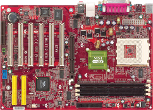
Examine your Mainboard closely to get a good feel of it's
layout. Match items on the Mainboard with those in the "Quick
User's Guide".
Properly mount the mainboard to the ATX case mainboard tray.
For the KT4V, use six metal standoffs with TWO WASHERS on
each standoff.
- One washer between the mainboard tray and standoff screw bottom.
- One washer between the standoff screw top and the mainboard.
This technique should assure zero chances of a ground
occurring.
Plug the CPU fan into CFAN1.
ATX Power Supply
Your KT4V will need a good name-brand 350W or better ATX power supply.
Inspect the power supply cables closely. Count how many 4-pin
power connectors you have. Count how many IDE optical devices and
hard drives you have. You can use a splitter if necessary, to
connect addition devices.
Plug in the 20-pin power connector at JWR1.
Most cases will come with a power supply. These
are usually only held in place with four screws. A good 350W or
400W power supply will only cost about $40-$60 US. A large
amount of KT4V problems are due to an inadequate power supply.
Front Panel Connectors
Plug in all Front Panel Connectors paying particular
attention to the wire pin definition chart in the KT4V Quick
User's Guide. The key to success here is to CAREFULLY
determine the PIN number by matching it with the corresponding Pin
Definition Signal. Believe it or not, IMHO this is the most
difficult procedure in the entire PC assembly process.
Don't worry about getting any of these
backwards; you cannot hurt anything here. If after your initial
boot something here doesn't
work properly, just shutdown the PC, turn the culprit connector around,
and reboot.
Inspect your IDE Devices
Inspect your IDE devices and ensure the jumpers are set to Master/Slave correctly.
Each device should have a legend on the attached factory sticker
explaining it's correct setting.
IDE-1 Master: Operating System HDD
IDE-2 Master: CD-rom or CD-RW, etc. If you have both it's your
call. Once your PC is stable run the CD reader as IDE-2 Master.
Inspect your IDE cables to ensure they are not damaged....
Don't use 66ATA IDE cables on a 133ATA IDE device....
Inspect your IDE cable length. Too long or too
short is not good. You want your IDE cables to be just long
enough to plug into the main board and the IDE device. To much
slack will be an eye sore and restrict case air flow.
One at a time, place your IDE devices into your ATX
case. Ideally you should leave them loose for now....so they can
slide forwards and backwards within their bays. This will help alot
when you attach the IDE and power cables. Attach the IDE and power
cables at this time. Then attach the device to the bay using two
screws on each side. Repeat for each device.
Floppy Drive
Place your floppy drive into it's bay.
When attaching the ribbon cable to the back of the
floppy drive, ensure the "twist" in the cable is on the
back-left of the unit. Later, if you find your floppy drive doesn't work, it may
be that the cable is on backwards.
Connect the power cable to the back of the floppy
drive.
Screw the floppy drive into the bay using two screws on
each side.
System fans
Install and plug in system fan(s). Utilize SFAN1
for your main system fan. The remainder will plug directly into
the power supply.
Components
During initial component installation DO NOT INSTALL EVERYTHING.
Barebones your PC. OS HDD, mouse, keyboard, and one CD-rom
device ONLY.
No PCI cards. No
joysticks. No Palm cradles. No printers.
No speakers, ETC. ETC.
Only side note here is use your onboard LAN or a 56K PCI modem (in Slot
1 or 4) or NIC to get on the internet. This barebones technique will become
very useful if troubleshooting is required. And it will not
strain your power supply on the initial boot.
Video Card
Plug your Video card into the AGP slot and connect the
monitor.
Very Important Step
Clear CMOS by using the "Quick
Reset" method.
DDR RAM
Place ONE DDR RAM stick into Slot1 (DDR1) on mainboard.
First Real System Test -
The Initial Boot
Set your PC upright and plug the power cord into the
back of the Power Supply. Plug the other end into an outlet.
Turn ON your monitor.
Press your PC "ON" button to Boot your PC.
Continuously hit the DEL key until the Bios Main Menu screen is displayed.
AMI Bios
|
If you are not familiar with the Bios Setup Menu
STOP and read "Bios Setup" in the KT4V "Quick User's
Guide". |
Upgrade to Bios v1.9. This
is how I flash my Bios.
Enter "Advanced BIOS Features" in Bios.
|
To enter Bios, press the "Delete"
key while your PC initially boots. |
Modify the
"Boot Sequency" for the Operating System (OS) you plan to install.
Set 1st
Boot Device to either "CD/DVD" or "Floppy", as follows:
For OS WIN XP select "CD/DVD" (WIN XP will boot
directly from the CD)
For OS WIN ME/98 select "Floppy" (a Boot disk is required for WIN
ME/98 OS installation)
At this time you will place the WIN XP Install CD into
the CD/DVD tray
or
If you will install WIN ME/98, place the Windows
"Boot" disk into the floppy drive.
Press ESC to return to Bios Main Menu.
Enter "PNP/PCI Configurations" and set "Primary
Graphics
Adapter" as AGP or PCI, as appropriate.
Press ESC to return to Bios Main Menu.
Enter "PC Health Status" and Check your CPU temp.
IMHO a temporary stable temp is anything less than 60c. If your
temps are above 60c you may have installed your heatsink
incorrectly. Fix it before continuing. Go here
to see how I fixed my high temps.
Press ESC to return to Bios Main Menu.
Select "Save & Exit Setup". All other Bios settings can
wait until later when your OS is installed and your system is stable.
Your PC will now "reboot" to
"CD/DVD" for WIN XP install or "Floppy" for WIN
ME/98 install.
Second Real System Test -
The Operating System
Installation
ALWAYS perform an OS Clean Install. Format and
partition the hard-drive (HDD) according to your preferences. If
you experience problems here call Microsoft :)
If you are installing OS WIN XP I recommend using
"NTFS" on the primary petition.
After the OS has been installed let the PC run for
a little while.
Check for stability
If your system is stable for ten minutes go back
into Bios and set CPU FSB Clock to appropriate setting.
Reboot and check for stability.
Once your PC is in Windows and is stable follow my other Bios
suggestions.
Reboot and check for stability.
Driver Installation
Install drivers from the KT4V CD or download from net.
Having these available before hand is a good idea and much quicker.
- Via 4-in-1 v4.47 (www.viaarena.com)
- Via LAN Driver v3.13
- Via USB 2.0 patch
- AC97 Sound card
Install
all Windows Updates from net.
Adding other
devices
Once your PC is stable you can add your other DDR/HDD/devices
one at
a time. Reboot each time and watch for stability
problems. When adding additional devices watch your IDE settings (master/slave) to avoid
IDE conflicts.
Always power down your PC and unplug the
power cord when entering your ATX case.
IF YOUR PROBLEM IS HEAT RELATED: These boards initially had
problems that
are heat-related. You MUST get your temps under control.
Install PCAlert4 for temperature viewing in Windows. Your PC will be
stable once your idle CPU temp is in the mid-50c's. See
my photo section to see how I got my temps from 61c to 36c.
|